7 TEK benchmarking with GENE in DIII-D cyclone base case

The DIII-D cyclone base case is a circular and concentric magnetic configuration. The main parameters are summarized in Table 1. All parameters are the same as those in T. Gorler’s paper[4]. (This configuratgion was inspired by DIII-D H-mode discharge #81499 and used in the cyclone project for benchmarking various gyrokinetic ITG turbulence simulations.)


R0 a r0 q0 ŝ0 BaxisˆκTiR0ˆκniR0 Ti0 qiTi0(eTe0)


1.67m0.60m0.30m1.410.84 2.0T 6.96 2.23 2.14keV 1


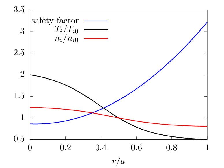
Table 1: DIII-D cyclone base case parameters[2][4] where R0 is the major radius of the magnetic axis, a is the minor radius of the last-closed-flux-surface, q0 is the value of safety factor at r = r0 = 0.5a, ŝ0 is the value of the magnetic shear ŝ = rq1dq∕dr at r = r0. Baxis is the magnetic field strength at the magnetic axis. The toroidal field function g(r) = BϕR is assumed 
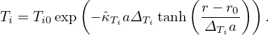
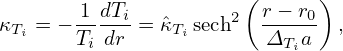
to be a constant independent of r, i.e., g = BaxisR0. Ti0 is the ion temperature at r = r0. Assume Deuterium plasma, then R0∕ρi = 500 and a∕ρi = 180. where ρi = ∘ ------
  Ti0∕mi∕Ωi is the thermal ion gyro-radius, Ωi = Baxisqi∕mi is the ion cyclotron angular frequency at the magnetic axis.

The safety factor profile is chosen as [6]

                            2
q(r) = 0.86− 0.16r∕a+ 2.52(r∕a)

This profile gives q0 q(0) = 1.41 and ŝ = 0.84 at r = r0. The equilibrium ion temperature and number density profile are given by

          (              (r − r0) )
Ti = Ti0exp − ˆκTiaΔTi tanh -----    .
                           ΔTia
(283)

          (              (      ))
                          r-−-r0
ni = ni0exp − ˆκniaΔni tanh  Δnia    .
(284)

where ΔTi = Δni = 0.3, ni0 = 4.66 × 10¹⁹m3, Ti0 = 2.14keV. Then the radial derivatives are written as

                        (      )
dTi = T(− ˆκ aΔ  )-d tanh  r−-r0
 dr    i   Ti  Tidr       ΔTia
                     2( r−-r0) --1--
    = Ti(− ˆκTiaΔTi) sech   ΔTia   ΔTia
                ( r− r )
    = − TiˆκTi sech2----0
                   ΔTia

The corresponding gradient scale lengths of Ti and ni are then given by

                      (      )
κTi = − 1-dTi = ˆκTi sech2 r−-r0 ,
       Ti dr             ΔTia
(285)

and

                      (      )
       1-dni         2  r−-r0
κni = − ni dr = ˆκni sech Δnia   ,
(286)

where sech2() 1 tanh2(). The electron density and temperature profiles are assumed to be identical to those of ions. The electron mass is set as me = 1.82 × 1030kg, i.e., two times the realistic value of electron mass.

The profiles of safety factor, temperature, and density are plotted in Fig. 3.


pict

Fig. 3: Radial profiles of safety factor, temperature, and density of the above DIII-D cyclone test case. The dashed lines indicate the radial simulation box 0.3 r∕a 0.7.


pict

Fig. 4: Benchmarking of TEK code with GENE for the ITG-KBM transition. Upper panel: growth rate; lower panel: angular frequency.


pict


Fig. 5: ITG-TEM transition benchmarking

Mode structures:


pict pict

pict 1.6022d-16pict

pict pict


Fig. 6: ITG  n = 20.

ITG-KBM transition:


pict pict

Fig. 7: itg-kbm transition, seems to succeed, to be continued. left: real me, right: half me,(3) increase radial resolution bottom left: δϕ, bottom right: δA.


pict pict


Fig. 8: δA and δΦ for ne∕nref = 2.4


pict pict

pict pict

pict pict


Fig. 9: equal-arc-length poloidal angle. δϕ and δA at n∕nref = 2.4.


pict pict

pict pict

pict pict

Fig. 10: The same as Fig. 9 excep the radial range is narrowed.