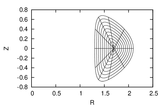
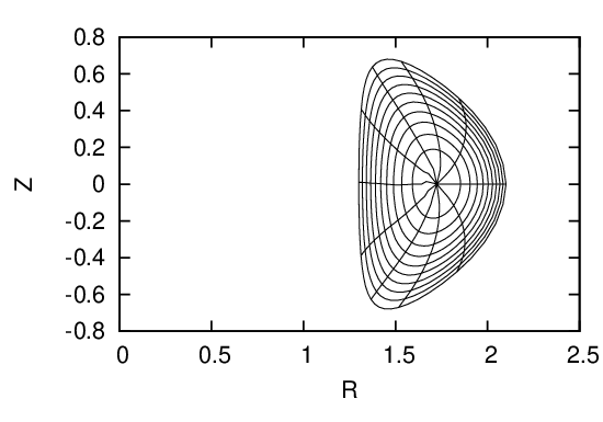
Fig. 30: Upper left figure plots the initial coordinate surfaces. After solving the GS equation to
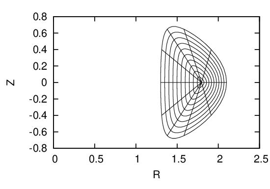
obtain the location of the magnetic axis, I shift the origin point of the initial coordinate system
to the location of the magnetic axis (upper right figure). Then, reshape the coordinate surface so
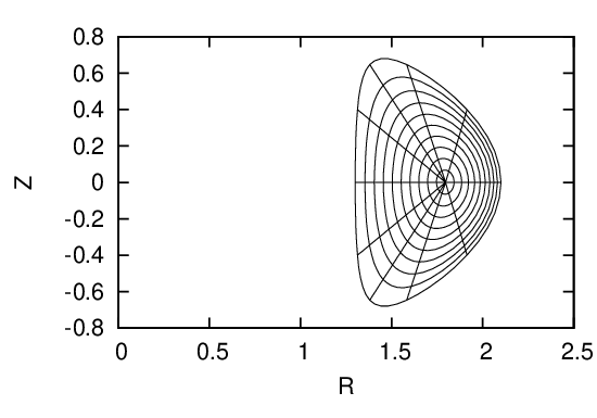
that the coordinate surfaces ψ = const lies on magnetic surfaces (middle left figure). Recalculate
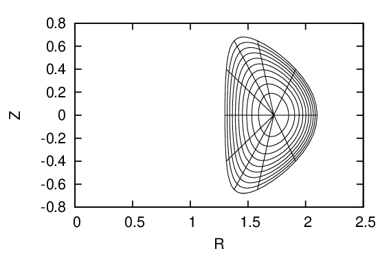
the radial coordinate ψ that is consistent with the Jacobian constraint and interpolate flux
surface to uniform ψ coordinates (middle right figure). Recalculate the poloidal coordinate 𝜃 that
is consistent with the Jacobian constraint and interpolate poloidal points on every flux surface
to uniform 𝜃 coordinates (bottom left figure).