In the fixed boundary equilibrium problem, the shape of the boundary magnetic surface (it is also the boundary of the computational region) is given while the shape of the inner flux surface is to be solved. A simple analytical expression for a D-shaped magnetic surface takes the form
 | (428) |
 | (429) |
with 𝜃 changing from 0 to 2π. According to the definition in Eqs. (29), (30), and (32) we can readily verify that the parameters a, R0, κ appearing in Eqs. (428) and (429) are indeed the minor radius, major radius, and ellipticity, respectively. According to the definition of triangularity Eq. (31), the triangularity δ for the magnetic surface defined by Eqs. (428) and (429) is written as
 | (430) |
Another common expression for the shape of a magnetic surface was given by Miller[8, 20], which is written as
![R = R0 + acos[𝜃+ arcsin(Δ sin𝜃)],](tokamak_equilibrium562x.png) | (431) |
 | (432) |
Note that Miller’s formula is only slightly different from the formula (428). For Miller’s formula, it is easy to prove that the triangularity δ is equal to Δ (instead of δ = sinΔ as given in Eq. (430)).
In the iterative metric method[11] for solving the fixed boundary equilibrium problem, we need to provide an initial guess of the shape of the inner flux surface (this initial guess is used to construct a initial generalized coordinates system). A common guess of the inner flux surfaces is given by
 | (433) |
 | (434) |
where α is a parameter, ψ is a label parameter of flux surface. If the shape of the LCFS is given by Eqs. (428) and (429), then Eqs. (433) and (434) are written as
 | (435) |
 | (436) |
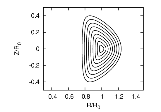
Fig. 29 plots the shape given by Eqs. (435) and (436) for a =0.4, R0 = 1.7, κ = 1.7, Δ = arcsin(0.6), and α = 1 with ψ varying from zero to one.

