D Coordinate system and grid in TEK code

In the magnetic coordinates (ψ,𝜃,ϕ) used in TEK code, ψ is the normalized poloidal magnetic flux, ψ = (Ψ Ψaxis)lcfs Ψaxis), 𝜃 is increasing along the anti-clockwise direction when viewed along ϕ direction, ϕ is the toroidal angle of the right-handed cylindrical coordinates (R,ϕ,Z). In this convention the Jacobian of the (ψ,𝜃,ϕ) coordinate system, 𝒥 = (ψ ⋅∇𝜃 ×∇ϕ) is negative, i.e., (ψ,𝜃,ϕ) is a left-handed system. The field-line-following coordinate system (ψ,𝜃,α) is also a left-handed system. The coordinate system (x = ψ,y = α,z = 𝜃) is a right-handed system.


PIC

Figure 3: Poloidal grid for equilibrium quantities used in TEK and GEM code. The array starts at 𝜃 = π and ends at 𝜃 = +π (𝜃 = ±π is chosen to be at the high-field side midplane in both the codes). TEK array index starts from 1 whereas GEM array index starts from 0. Hence mpol=nth+1. nth is denoted by ntheta in GEM. I do not need to make connection with GEM’s equilibrium poloidal array because there is no coupling of equilibrium quantities between the code written by me and the original code in GEM. The coupling happens for the perturbed quanties, whose poloidal grids need to be consistent. TEK poloidal grid-points for perturbation are indexed as 0:mpol2 with the index 0 corresponding to 𝜃 = π and the index mpol2 corresponding to 𝜃 = +π. Field equation is solved at 0 : mpol2 1. (The field at mpol2, i.e., 𝜃 = +π, is obtained by inerpolating the field at 𝜃 = π.) mpol2 is determined by mpol2=numproc/ntube, i.e., mpol2 is the total number of cells along the 𝜃 direction use for MPI parallelation. mpol and mpol2 must be chosen in a way that makes (mpol-1)/mpol2 be an integer, which can be larger than 1, i.e., one simulation cell can span several equilibrium cells.


pict

Figure 4: Radial grid used in TEK. Two radial arrays are used in the code, radcor_1d_array(1:nt) and radcor_1d_array2(1:n), equilibrium is defined on the former grid, and perturbations are defined on the latter grid. Here nt = n + 2m, m is the number of grid points in one of the two buffer regions (regions in blue color). In the code n is denoted by nflux2 and nt is denoted by nflux, m is denoted by points_in_buffer. In GEM the radial array does no include the buffer regions and the index starts at 0 and ends at imx. Hence n=imx+1.


pict

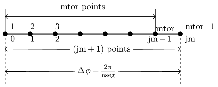
Figure 5: Toroidal grid used in TEK and GEM. TEK array index starts at 1 whereas GEM array index starts from 0. In TEK, the toroidal array is tor_1d_array(1:mtor+1). source terms, δn and δj, are defined at 1:mtor; EM fields are defined at 1:mtor+1. GEM array ends at jm. It follows that mtor=jm.


GEM array index system is better than TEK’s because my system is not consistent: sometimes I use 0-based index and sometimes I use 1-based index, sometimes the index ends at n and sometimes ends at n+1. It is important to know accurately the transformation between the two systems.